![]()
![]()

We need your help! 🔥
Please consider disabling your ad-blocker to support this website! 🔑
We are a free, community-supported website! 🥰
We only display small unobtrusive ads which help us stay online! 💯
Thank you in advance! ❤️
We are a free, community-supported website! 🥰
We only display small unobtrusive ads which help us stay online! 💯
Thank you in advance! ❤️
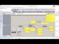
Model View (Karamba3D_PUI)
Lets you inspect the current state of the model.
Plug it into the data pipeline in front of 'Beam View' or 'Shell View' to control the overall model display.
Inputs
| Name | ID | Description | Type |
|---|---|---|---|
| Model | Model | Model to be viewed | Model |
| Displacement Direction | DispDir | Input a vector for specifying the direction of the displacement component to be displayed. Alternatively supply a plane to project the displacements on it. By default the resultant displacements are shown. | Generic Data |
| Result-Factors | R-Factors | List of factors for scaling results of one or several result-cases. In case this is a list each factor is applied to the corresponding load-case. Select ---all--- in drop down list for load-cases to superimpose them. | Number |
| Result-Case | ResCase | This number is added to the visible result-case index selected at the result-case drop-down-list of the ModelView-component. Default value '-1' displays '--all--'. | Integer |
| Colors | Colors | This list of colors is used for rendering colored meshes. The first color is used for values below the currently visible range. The last color is used for values above the currently visible range. All other colors are evenly distributed in the visible range. The minimum number of colors to be supplied is four. | Colour |
| Element Identifiers/Breps | Ids|Breps | List of identifiers of elements which shall be displayed and/or Breps which define visibility via the element nodes inside them. By default all elements are displayed. In case identifiers and Breps are given only those elements are visible which fulfill both criteria. | Generic Data |
| Deformation | Deformation | Activates/deactivates the display of deformed state. | Boolean |
| Deformation Scale | Deformation Scale | Scales the deformation. '1' corresponds to the real displacements. | Number |
| Reaction | Reaction | Activates/deactivates the display of reaction forces and moments at supports. Green arrows stand for forces in the direction of the arrow. Purple arrows for moments about the arrow axis. | Boolean |
| Reaction Scale | Reaction Scale | Scales the symbols for reaction forces/moments at supports. Green arrows stand for forces in the direction of the arrow. Purple arrows for moments about the arrow axis. | Number |
| Loads | Loads | Activates/deactivates the display of loads. | Boolean |
| Loads Scale | Loads Scale | Scales load symbols. | Number |
| Supports | Supports | Activates/deactivates the display of support conditions. | Boolean |
| Supports Scale | Supports Scale | Scales support condition symbols. | Number |
| Local Axes | Local Axes | Activates/deactivates the display of local element coordinate systems. Red/Green/Blue corresponds to local X-, Y-, and Z-axis. | Boolean |
| Local Axes Scale | Local Axes Scale | Scales the local element coordinate system symbols. Red/Green/Blue corresponds to local X-, Y-, and Z-axis. | Number |
| Joints | Joints | Activates/deactivates the display of joint symbols. Pink circle stand for released rotations, light yellow arrows for released translations. | Boolean |
| Joints Scale | Joints Scale | Scales the joint symbols. Pink circle stand for released rotations, light yellow arrows for released translations. | Number |
| Length/Segment | Length/Segment | Scales the length [m] of segments of deformed beams. Reduce this value to make the deformed shape of beams appear smoother. '0' means no segmentation. | Number |
| Upper Result Threshold | Upper Result Threshold | Scales the numerical range of displayed results. | Number |
| Lower Result Threshold | Lower Result Threshold | Scales the numerical range of displayed results. | Number |
| Result Threshold as | Result Threshold as | Sets interpretation of results thresholds. '0' - % of Range; '1' - absolute value | Integer |
| Node tags | Node tags | Enables/disables the display of node numbers. Nodes are numbered consecutively starting from '0'. | Boolean |
| Element tags | Element tags | Enables/disables the display of element numbers. Elements are numbered consecutively starting from '0'. Meshes count as one element. | Boolean |
| Element IDs | Element IDs | Enables/disables the display of element IDs. Elements can be given non-unique names on creation. These can be used for reference single elements and element sets. Regular expressions as references (they start with '&' and correspond to Perl syntax) can be used to construct sets. | Boolean |
| CroSec Names | CroSec Names | Enables/disables the display of cross section names. | Boolean |
| Material Names | Material Names | Enables/disables the display of material names. | Boolean |
| Eccentricities | Eccentricities | Enables/disables the display of eccentricity symbols. | Boolean |
| Load Values | Load Values | Enables/disables the numerical display of load magnitudes [kN] and point masses [kg]. | Boolean |
| Elements | Elements | Enables/disables the output/display of deformed element axes at the 'def.Curves' output-plug. | Boolean |
| NII | NII | Enables/disables the numerical display of NII [kN] which is the normal forces used to calculate ThII effects. | Boolean |
| Cross Section Color | Cross Section Color | Set here the display of cross section colors. '0' - None; '1' - Elements; '2' - Cross Sections; '3' - Materials | Integer |
Outputs
| Name | ID | Description | Type |
|---|---|---|---|
| Model | Model | Model | Model |
| Deformed mesh | defMesh | Mesh of deformed structure | Mesh |
| Deformed axes | defAxes | Axes of deformed structure (if enabled - see 'Elements' check-box) | Curve |
| Deformed model | defModel | deformed Model with nodal displacements as displayed | Model |


Site design © Robin Rodricks.
Karamba3D and associated data © 2025 Clemens Preisinger.
Rhinoceros and Grasshopper are registered trademarks of Robert McNeel & Associates.
Hosted by GitHub